Module 11 - On Site Activities beyond calibration
Preparing to Commence Activities on site
Before starting any work, undertake the following with the local site representative:
- Secure the necessary Work Permits with the appropriate Risk Assessment and Method Statement.
- Perform a Place of Work Job Safety Analysis on reaching site.
- Hold an onsite Job Safety briefing / toolbox talk – this should be held daily.
- Ensure that all members of the working party know what is expected of them, have the correct PPE for the job and are fully briefed on any risks.
Stop work if you are at all unhappy with the conditions and report back to OptaSense and the Client PM.
Before the commencement of any work perform a check on the power source using the standard toolkit mains checker, this will detail the earth status of the power source. Do not proceed if the response is not an immediate set of green lights – under no circumstances should the IU, or any other equipment, be connected to an un-earthed power supply. Seek advice.
Gather and analyse the equipment drawings to familiarise yourself with both the asset and location installation plans.
Ensure you have the full detail available of any outstanding punch list items or comment sheets on drawings. Refer to the OptaSense ticketing system for information. Also ensure that you have the necessary items to perform the works expected. Check your OptaSense toolkit against the latest specification.
Obtain the latest software versions required for both Windows and Linux. If the operating system and OptaSense version number are current and the latest standards, confirm that the operating system machine licences are accessible to ensure that a rebuild can be completed onsite as required.
Site Inspection
A site inspection may have been completed before the project started. If this is the case, ensure that a copy of the report is available so that the actual findings (and recommendations) made during the survey can be checked against what is found on site during the installation.
- Assess the infrastructure (racks etc.), refer to installation diagrams (rack diagram) provided in-house or by the client.
- Check all equipment is available and easily accessible with enough physical room for the equipment and cable runs are neat and tidy with no obvious cable strain or tight bends.
- Ensure that the cooling/air conditioning is as required, both in the room that the equipment is located (CCR, TER etc) and also that the rack ventilation/through-flow are sufficient for the Integrator Unit (IU).
- If an Uninterruptible Power Supply (UPS) was expected as part of the project scope ensure that this is available and record details such as maximum power voltage, supply duration, and IP addresses (if ethernet controlled).
- Check routing of the fibre optic patch cord from IU connection to sensing fibre. Preferably this will be connected via a fusion splice, if a patch panel is installed confirm type of connector (E2000-APC type recommended, minimum APC required). Ensure that the minimum optical distance between first connector/splice is 30m from the IU, record fibre routing and length. Check the general fibre hygiene and clean connectors as required.
- Discuss with the client if any modifications have been performed on the system and that these have been specified in the requirements register.
- Check with the client’s IT manager that the expected IP addresses for the equipment as specified on the OptaSense Network Diagram are in fact free. Double check by connecting to network using a free IP address and PING the addresses required to confirm they are not currently utilised – or run an IP checking script to verify what nodes are connected.
- Has the client provided system passwords for User and Administrator levels? If not, note the defaults that are applied. Ensure that there is a reserved password for the (Optasense) engineering log in if provided. During installation these can be utilised as standard however at the end of the installation these must be set to the required values. (Passwords should ONLY be changed using the password change tool on the Windows desktop (part of the bespoke OptaSense installs - NOT the standard password control section of Windows).
Rack Population Planning
The order of IU/node installation will depend on the requirements of the project plan. For example, the plan to install all equipment then perform a calibration or to perform a rolling installation/calibration. For large jobs (>5 IU’s) a full installation plan should be provided by the project manager. This may be specified in a site drawing. It is worth noting that a rolling installation will require constant changes to the system descriptor as the nodes will have to be added as the project progresses. The database will be refreshed every time a node is added.
In the outline provided below, the latter is assumed, but the requirements are the same in each case.
- Perform physical checks – taking care to ensure there are sufficient power outlets for the equipment. Consult the rack drawing.
- Consult the IU manual for detailed information on deployment requirements.
- Install equipment following manufacturer’s instructions (3rd party kit), rack drawings, Installer’s Manual and system drawings.
- Install Ethernet Switch (assumed all kit running from UPS).
- Install Ethernet Controlled Power supply.
- Install IU’s ensuring airflow requirements specified in manual (normally achieved through VBIS – consult Installation Guide for full instructions). Under no circumstances is the IU to be installed in a manner in which the bolts at the front support the weight of the IU. The system should seated directly on the VBIS or be rail mounted if this is requested by the customer.
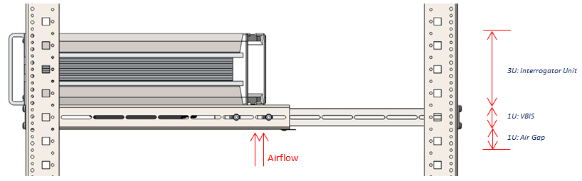
Figure 1: Important considerations for IU
Either by using a diagnostic laptop, or by coordinated assistance from the control room, perform the following initial tests:
- Perform ping tests to all equipment.
- Test remote power cycling afforded by Putty.
- Test remote power cycling afforded by ECPS (note this should NOT be used as a matter of course – only rare (and unforeseen) conditions will be resolved by ECPS power cycling, the default position should be to use Putty – or better still solve your problems in software).
- Verify expected behaviour of laser on Interrogator waterfall display.
Every installation will be different but ensure that the weight is at the bottom of the rack if possible and that the rack is adequately earthed.
Ensure that the IU is mounted on a VBIS and that there is adequate airflow and that there is adequate cooling i.e. air Conditioning in hot countries.
Connect the network cable from the IU to the server unit and check network communications between server and IU are achievable before leaving site.
Detector Testing and Tuning
This manual is NOT intended to cover the tuning of each detector type as that is covered through longer term training, engineering training courses and engineer’s notes.
Following the previous Module (Module 10 – Calibration and Geo-Referencing Procedure) should result in a calibrated system with most of the necessary information required for the skilled engineer to complete the tuning on each of the detectors.
The remainder of this chapter provides guidance on testing the detectors once initially tuned.
Testing the detector types
With this first pass of information, we can test in suitable locations (identified earlier) the performance of each detector instance. During the first exercise we will no doubt make some changes that will need to be broadcast to every OPS (large scale changes) – use the settings promulgation controls built into each detector.
We should also perform some tests for EACH OPS. We don’t want to be modifying global settings at this point, but if a specific instance requires modification for a detector then that is acceptable (changes will be OPS specific) – if you find that you need an additional detector instance to cover an OPS then this addition will be implemented on every OPS. The additional detectors can still be disabled on an individual OPS basis.
Tests should be carried out in a realistic manner – i.e. digging a hole rather than simulated ground strikes.
The tests can also be used to identify suitable locations for SAT testing – 4 to 5 per OPS.
Mechanical Digging Methodology
Decide (based on the background acoustics: tonal presence, clutter) whether a “Mechanical Digger” or “Pipeline Activity” approach will be taken to detect the presence of such pipeline disturbances. Whilst much of the mechanical digging methodology is like that of the manual digging, there is the added dimension of the tonal assessment.
- Locate asset (e.g. pipeline by tracker) and fibre (acoustically)
- Commence by locating the pipe (fibre) and marking out appropriate ranges from the asset – e.g. 0m, 5m, 10m.
- Perform the following tests (recorded – and preferably on video as well) for the purpose of assessment:
- Digger starts up and idles at each distance from the asset, later it varies engine pitch, later it enables hydraulics.
- Digger drives parallel to asset at each distance from the asset and finally crosses the asset from greatest extremity.
- Digger parked at distance from asset, fires up, locates itself for digging (e.g. places anchors), stabilises with bucket, commences digging a trench with backhoe – to approximately the depth of the asset and makes a trench long enough to involve repositioning of digger.
Repeat as required in order to satisfy client requirements.
The following analysis points should be made during the recording:
- Observe analysis screen on channel and look for the presence of engine tones – note levels and frequencies at different ranges.
- Observe similar data for the presence of transients from digging activity – looking also at digging detector within mechanical digging
- Alter settings (in accordance with manual) to ensure that the correct activity is detected with a minimum of background activity.
Always record the data and utilise the replay functions to modify the detector settings rather than attempting to tune all of the settings in a live environment.
Again, it is likely that more than one detector area will be required to accommodate sensitivity variations along the fibre.
Additional Detectors
Other detectors (e.g. vehicle / personnel) can be calibrated rather more simply by performing sample excitation and test type activities (again modulated as required with knowledge of the underlying acoustic sensitivity). Follow the instructions in the manuals for each detector type.
For Personnel and Vehicle, we can also setup detector areas to vary the thresholds and other settings over an individual OPS:
- Do a test towards the end of fibre and setup the detector to detect – this may require quite low thresholds.
- Observe the performance of the thresholds with distance – there will be a general increase in signal closer to the start of the detector and it is likely that more than one detector area will be required. Judge this from the detector threshold chart and from repeated testing and indeed from background alerts appearing (typically around 1000 to 1500 channels is a good transition point or as required by specific environmental features).
- It should be straightforward to setup multiple detector areas.
- To limit processing, set thresholds high in areas where detection is not required as this will prevent unnecessary processing.
System Alert Assessment
From this initial data collection, we should have configured some alert types as well as geo-referenced the entire cable. Everything is now in place to complete the commissioning.
Review the data acquired during calibration and look for weaknesses – specifically are there environmental areas where the energy levels obtained would not be expected to result in alerts or would be marginal?
Consider how these should be treated?
- Change the alert settings to accommodate the weaker environmental areas?
- Set up a twin detection approach (Sensitive / Insensitive)
(Note that client requirements may require the provision of sensitive / insensitive alert settings anyway to cater for either suspect areas or day/night differences in approach)
Clearly changing the alert settings to accommodate weaker energy levels will result in detection from a greater distance in the stronger areas – this must all be considered with respect to the programmed logic sequence (e.g. dig timing). It may be possible to weaken the threshold criteria without resulting in an excess of alerts. The main criterion to consider is the proportion of area valid for the initial detector settings.
If changes are required, the more detailed alert configuration noted above should be repeated at the observed weaker sites to establish a second set of alert data.
If the exact course of action is not clear, consider implementing both approaches for a period (a lower setting and a higher setting) in separate detectors to explore background false alert levels.
During the initial commissioning period it is of course not possible to fully assess the levels of false alarms, however a first pass on optimising the settings should be undertaken – following the process below:
- Leave alert settings implemented whilst other work is being performed (but with audio & display still muted)
- Investigate the quantity, distribution & behaviour of alerts to explore patterns:
- Are specific background activities creating alerts – i.e. is there confusion between the desired alert type and what activity is apparent
- Is there a trend in the data – e.g. diurnal (likely), spatial?
Once the reasons have been ascertained, modifications to the alert settings may be applied.
Once an effective set of operating conditions has been derived, a pre-SAT test may be conducted:
- Replicate the activities expected in the SAT (digging tests at a variety of locations).
- Confirm that an alert is produced.
- Perform remedial action if no alert is derived or if performance is noted to be marginal.
Pre-SAT & SAT
Once the system has been commissioned – perform a complete pre-SAT. The SAT document should have been approved well in advance by all parties. The pre-SAT should follow the same testing procedure as the SAT.
Any system adjustments are to be made during the Pre-SAT; the SAT will be performed with the customer witnessing. There should be no surprises.
Ensure all tests are recorded and properly documented.
Finalise the Installation
The following housekeeping tasks should be performed at the closure of a site installation:
- Start up a “Site Modification” record file on the desktop of the engineering logon – host the file on the server (a folder should already be available and a template in place) so it can be accessed anywhere, ensure there is a link on the desktop.
- Make a copy of the FINAL configuration (this can be excluding the maps if these already exist on Huddle). Upload to project workspace.
- Map a network drive on the server
- Ensure the following items are copied onto the network drive.
- Final version of the config
- Latest version of the drawings
- System Modification Document
- Copy of the permanent licence
- Complete your notes, including any comment sheet information or drawing revision requirements.
- Handover all documentation to the client
- Ensure handover paperwork from OptaSense is signed off by the client
- Check that all links to switches, ECPS, UPS servers etc. are in place and functioning as intended.
- Install permanent licences only when OptaSense has verified payment has been made (likely to be during support or can be enacted remotely).
- Ensure the correct accounts are set up in the OptaSense software which have the correct permissions – log out of OptaAdmin unless specifically told otherwise
- Upload report, schematics and copy of configuration files with note of software version number to the project workspace.